
This guide walks you through the full procedure to safely remove, clean, and replace the membrane on your 24-port K&A synthesizer main block.
There is also a video for this procedure here: K&A - Membrane Replacement
🔧 Tools and Supplies Needed
- 3 mm Allen Wrench
-
2.5 mm Allen wrench or Cordless power drill with 2.5 mm bit
Power drill runs the risk of overtightening the screw. Allen Wrench is recommended in most instances
-
8 mm wrench
-
Guitar string or similar flexible wire
-
Lint-free wipes
-
ACN (acetonitrile) or ethanol
-
Replacement membrane
-
Spare caps for sealing chemical bottles when instrument is unpressurized
-
Replacement M3 screws and flangeless fittings (if needed)
-
Access to PC with K&A control software
⚠️ Warnings
-
Always fully shut down and depressurize the instrument before disassembly.
-
Use caution with chemicals—seal bottles if left open.
-
Do not overtighten screws or fittings.
-
Use the correct torque setting on the drill to avoid damaging screw threads.
1. Shut Down and Prepare
-
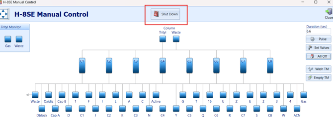
In the Software, open the Manual Control Screen and click SHUT DOWN.
-
Follow all on-screen prompts until all the liquid is in their respective bottles.
-
Double check to make sure no fluid remains in the liquid or waste lines.
-
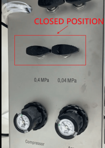
Once the lines are dry, close the Argon and Compressor Pressure Turn Valves
WARNING: FAILURE TO DO THIS CORRECTLY COULD LEAD TO CROSS CONTAMINATION OF REAGENTS. NEVER TURN OFF COMPRESSOR PRESSURE UNTIL ALL BOTTLES HAVE BEEN DEPRESSURIZED
2. Secure Chemicals
-
Remove all reagent and amidite bottle caps and seal the bottles with spare caps to prevent chemical degradation.
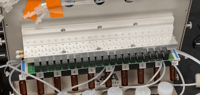
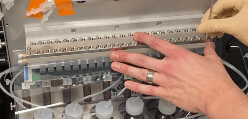
3. Disassemble the Manifold Block
-
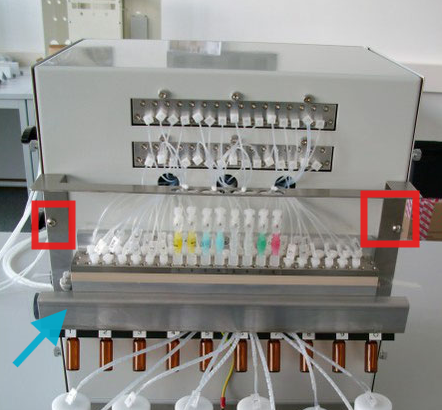
Remove the sheet metal loom above the column area using the 3.0 mm Allen Wrench
-
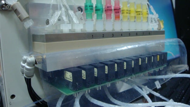
Loosen the fittings on the main block, and fully remove the column inserts. Tape can be used to hold the lines in place after detaching.
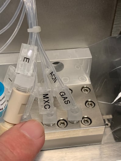
Hint: Take pictures and ensure the lines are fully labeled so that you return the fittings to the correct spot
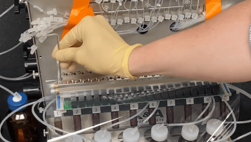
-
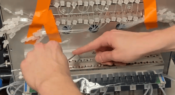
Use a 2.5 mm Allen wrench to begin loosening the manifold screws. A cordless drill (2.5 mm bit, torque = 0) can also be used to fully remove all screws.
WARNING: It is very easy to strip the screws so use allen wrenches or bits that are not worn
-
Inspect all screws—replace any with damaged heads.
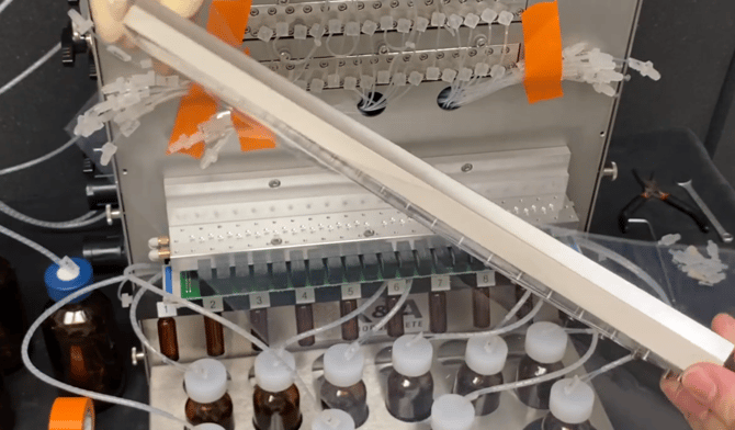
4. Clean Components
-
Remove the PEEK channel block and clean with ACN and a lint-free wipe.
-
Clear all ports on the PEEK channel using a guitar string to remove debris or blockages.
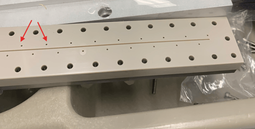
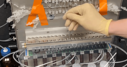
5. Replace Membrane
-
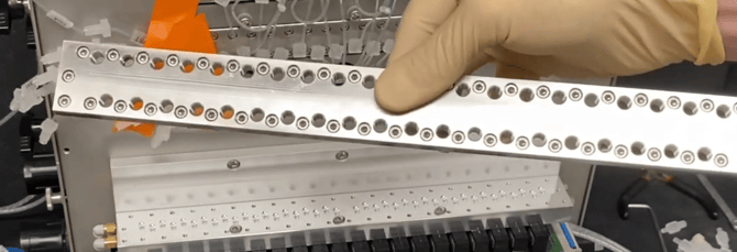
Remove the old membrane and align the new one so screw holes match the block pattern.
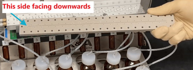
-
Place the membrane beneath the PEEK channel block and the valve block—make sure the channels on the Peek Manifold face downwards. The channels should face the membrane.
-
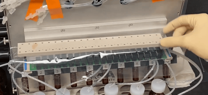
Insert the screws through the top manifold plate, using the holes to line up the membrane.
6. Reassemble Manifold Block
-
Start one screw at each end by hand using the 2.5 mm Allen wrench.
-
Lightly insert remaining screws starting from the center outward to evenly distribute torque
-
Tighten all screws by hand to finish—do not over-tighten.
🔁 Repeat this full process for any upper valve blocks or multiple membranes that need replacement.
7. Inspect and Replace Fittings
-
Inspect male luer fittings under each column. Replace if needed.
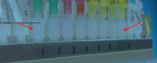
-
Use a guitar string to clear any new fittings before installing.
-
Use an 8 mm wrench to reinstall and tighten all fittings.
-
Replace damaged fittings with flangeless spares as necessary. Refer to this Video if a fitting replacement is needed.
8. Re-Pressurize and Test
-
Turn the compressor air valve back on.
-
Listen for leaks—tighten or replace fittings if needed.
-
Reinstall the sheet metal loom and column adapters.
-
On the PC, go to Control > Manual Control to verify tubing layout and placement of lines on the manifold.
-
Reconnect reagent/amidite lines and prime all channels.
-
Again inspect for liquid leaks.
Final Notes
- Label the lines for easier placement,
-
This membrane change procedure helps maintain consistent flow and synthesis quality.
-
If you're unsure at any step, contact Sierra BioSystems Support or refer to your K&A service manual.
-
Consider logging the procedure in your maintenance records, including membrane part number and date changed.